Bolid autonomiczny - regulamin (ENG)
Categories:
Bolid Autonomiczny
Znajdują się tutaj wszystkie fragmenty FS Rules które dotyczą bolidu autonomicznego w wersji cytowanej.
Wersja angielska (cytowana):
A 4.1.1 A university can register one CV team and one EV team which both can take part in the DC.
A 4.4 Autonomous System Responsible
A 4.4.1 To operate the AS, every participating team must appoint at least one ASR for the competition.
This person is responsible for all autonomous operations of the vehicle during the competition
which includes any work on the autonomous system as well as racing and testing.
A 4.4.2 For vehicles with an electric drivetrain the ASR must fulfill A 4 .3 and therefore replaces the
ESO. The team may register additional ESOs for accumulator inspection and work on Tracktive System (TS) only. The sum of registered ASRs and ESOs must not exceed four persons.
A 4.4.3 The ASR is the only person in the team who is allowed to declare the autonomous system
safe, so that the vehicle may be operated in manual or autonomous mode.
A 4.4.4 The ASR must be a valid team member, which means that he/she must have student status,
see A 4.2.6.
A 4.4.5 The ASR must accompany the vehicle whenever it is operated or moved around at the
competition site.
A 4.4.6 If only one ASR is named by the team, this ASR may not be a driver.
A 4.4.7 The ASR must be properly qualified to handle the autonomous system and to understand
and deal with problems and failures. As ASR Qualification (ASRQ), a bachelor degree in
computer science, electrical engineering, mechatronics, automation engineering, robotics
or similar (i.e. comparable study content or progress) is a sufficient qualification. The
qualification certificate needs to be an official university document and contain information
on completed courses.
A 5.6.2 [DC ONLY] At the end of the VSV, the vehicle must be stopped by an emergency
brake maneuver (see T 15).
A 5.6.3 Autonomous Vehicle is required to have Autonomous System Status Indicator (ASSI)
A 5.6.3 [DC ONLY] In addition to the third person view, an onboard view and a visualization
of the vehicle’s environment perception and path planning must be shown in split
screen. All parts must be time synchronized.
[DC ONLY] Vehicle must drive without a driver
A 5.6.6 If a team fails only the [DC ONLY] part, it will only be de-registered from the DC.
A 6.3.2 All ASRs are required to attend the team briefing.
A 6.7.3 Vehicles must also have their autonomous system (see definition in T 14 .6) deactivated when being moved around the paddock. The ASR must ensure no unauthorized activation of the Autonomous System Master Switch (ASMS) following T 14.6.8.
T 1.4 Driving Mode Definitions
T 1.4.1 Manual Mode – A vehicle is in manual mode when driven by a human driver. In this case
the ASMS must be off (AS deactivated).
T 1.4.2 Autonomous Mode – A vehicle is in autonomous mode when the AS is activated. When a
vehicle is in autonomous mode, there must be no person inside the vehicle.
T 2.8.1 Steering systems using cables or belts for actuation are prohibited. This does not apply for autonomous steering actuators.
T 11 ELECTRICAL COMPONENTS
T 11.10 System Status Light
T 11.10.1 Any system status light(s), see T6.5 and T14.11 must meet the following requirements:
- Black background
- Rectangular, triangular or near round shape
- Minimum illuminated surface of 15cm^2 with even luminous intensity
- Clearly visible in very bright sunlight
- If LED lights are used without a diffuser, they must not be more than 20mm apart
- If a single line of LED lights is used, the minimum length is 150mm
T 14 AUTONOMOUS SYSTEM
T 14.1 Definitions
T 14.1.1 Each vehicle must implement a full AS according to T 14, to run in autonomous mode.
T 14.1.2 [CV ONLY] The following definitions apply to maintain the same wording as for Electric
Vehicles:
- Ready-to-drive (R2D) – Engine is running and a gear is engaged.
- TS active – Engine is running but gearbox is in neutral (also assumed for TS not active).
- TS activation button – The engine start button is the equivalent.
- Accumulator Isolation Relay (AIR) - The fuel pump relay (see Figure 21) is the equivalent.
T 14.2 Teleoperated driving
T 14.2.1 Teleoperated driving is not allowed.
T 14.3 Data logger
T 14.3.1 The officials will provide a standardized data logger that must be installed during the
competition. Further specifications for the data logger and required hardware and software
interfaces can be found in the competition handbook.
T 14.3.2 The team needs to provide two sets of signals to the data logger:
- Basic set of signals as defined in the competition handbook
- Vehicle-individual set of signals that is monitored by the ASB to ensure redundancy and fault detection
- [CV Only] The mounting of data logger must be sealed during technical inspection.
T 14.4 Remote Emergency System
T 14.4.1 Every vehicle must be equipped with a standard RES specified in the competition handbook.
The system consists of two parts, the remote control and the vehicle module.
T 14.4.2 The RES must be purchased by the team.
T 14.4.3 The RES has two functions:
- When the remote emergency stop button is pressed, it must open the SDC defined in T 14.5.
- When the “Go” button is pressed, the preselected autonomous mission is started.
T 14.4.4 The RES vehicle module must be directly integrated in the vehicle’s SDC with one of its
relays hard-wired in series to the shutdown buttons.
T 14.4.5 The RES relay, which is integrated into the SDC, may be bypassed by a normally closed
relays, when driving manually. The relay must:
- be directly supplied by the ASMS, see T 14.7
- have a safety certified forcibly guided or a mirrored normally open contact which is directly connected in series to the ASMS
T 14.4.6 The antenna of the RES must be mounted unobstructed and without interfering parts in proximity (other antennas, etc.).
T 14.5 Shutdown Circuit
T 14.5.1 The SDC may only be closed by the AS, if the following conditions are fulfilled:
- Manual Driving: Manual Mission is selected, the AS has checked that ASB is deactivated (No autonomous brake actuation possible).
- Autonomous Driving: Autonomous Mission is selected, ASMS is switched on and sufficient brake pressure is built up (brakes are closed).
T 14.6 Signals
T 14.6.1 Any signal of the AS is a SCS. If failures lead to loss of environment perception and/or
localization, the system must react accordingly.
T 14.7 Autonomous System Master Switch
T 14.7.1 Each vehicle must be equipped with an ASMS, according to T 11.2.
T 14.7.2 The ASMS must be mounted in the middle of a completely blue circular area of ≥50 mm
diameter placed on a high contrast background.
T 14.7.3 The ASMS must be marked with “AS”.
T 14.7.4 The power supply of the steering and braking actuators must be switched by
- LVMS
- ASMS
Other than stated in T 11.2.1, non-programmable logic may be used as part of the ASMS.
T 14.7.5 When the ASMS is in “Off” position, the following must be fulfilled:
- No steering, braking and propulsion actuation can be performed by request of the autonomous system.
- The sensors and the processing units can stay operational.
- The vehicle must be able to be pushed as specified in A 6.7.
- It must be possible to operate the vehicle manually as a normal CV or EV.
T 14.7.6 It is strictly forbidden to switch the ASMS to the “On” position if a person is inside the
vehicle.
T 14.7.7 After switching the ASMS to the “On” position, the vehicle must not start moving, until R2D
is entered (Figure 17).
T 14.7.8 The ASMS must be fitted with a “lockout/tagout” capability to prevent accidental activation
of the AS. The ASR must ensure that the ASMS is locked in the off position whenever the
vehicle is outside the dynamic area or driven in manual mode.
T 14.8 Steering Actuation
T 14.8.1 Steering system actuation (movement) must only happen if the vehicle is R2D.
T 14.8.2 The steering system may remain active during an emergency brake maneuver while the
vehicle is in movement.
T 14.8.3 Manual steering must be possible without manual release steps (e.g. operating manual valves
/ (dis-) connecting mechanical elements) while the ASMS is switched “Off”.
T 14.9 Actuator Decoupling
T 14.9.1 It is not allowed to remove any parts of the autonomous system for dynamic events.
T 14.9.2 The actuators may be disconnected for manual driving if:
- no parts including bolts, clips, etc. are removed for disconnection i.e. they must never loose the physical contact to the disconnection mechanism.
- the disconnection mechanism cannot block manual operation in any position.
- the disconnection mechanism is securely locked in both positions.
T 14.10 Autonomous System Status Definitions
T 14.10.1 The Emergency Brake System (EBS) is considered to be “activated”, if the power supply
path defined in T 15 .2.2 is cut after passing the initial checkup sequence ( T 15 .3.1). Brakes
may only be released after performing manual steps.
T 14.10.2 The status of the AS must be determined according to the flowchart below.
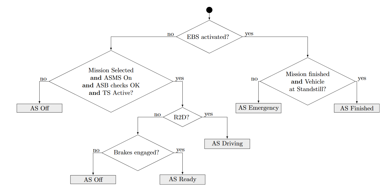
T 14.10.3 R2D may only be activated by the “Go” signal from the RES, after the system has remained
in “AS Ready” for at least 5 s.
T 14.10.4 Performing manual steps, other than activating the TS, at the vehicle while the ASMS is
switched “On” is prohibited.
T 14.11 Autonomous System Status Indicators
T 14.11.1 The vehicle must include three ASSIs that must indicate the status of the AS (as defined in
T 14.10) correlating to illumination as shown:
| AS Off | AS Ready | AS Driving | AS Emergency | AS Finished |
|---|---|---|---|---|
| off | yellow continuous | yellow flashing | blue flashing | blue continuous |
The ASSIs may not perform any other functions.
T 14.11.2 One ASSI must be located on each side of the vehicle behind the driver’s compartment, in
a region 160 mm below the top of the main hoop and 600 mm above the ground. The third
ASSI must be located at the rear of the vehicle, on the vehicle centerline, in a region 160 mm
below the top of the main hoop and 100 mm above the brake light.
T 14.11.3 At least one ASSI must be visible from any angle of the vehicle from a point 1.60m vertically from ground level, within 3m horizontal radius from the top of the main hoop.
T 14.11.4 Each ASSI must meet the requirements according to T 11.10.
T 14.11.5 The status “AS Emergency” has to be indicated by an intermittent sound with the following
parameters:
- on-/off-frequency: 1 Hz to 5 Hz
- duty cycle 50 %
- sound level between 80 dBA and 90 dBA, fast weighting in a radius of 2 m around the vehicle.
- duration between 8 s and 10 s after entering “AS Emergency”
T 14.12 Autonomous Missions
T 14.12.1 The AS must at least implement the following missions:
- Acceleration
- Skidpad
- [DC ONLY] Autocross
- [DC ONLY] Trackdrive
- EBS test
- Inspection
- Manual driving
T 14.12.2 The inspection mission is defined by slowly spinning the drivetrain and actuating the steering
system with a sine wave while the vehicle is jacked up and all wheels are removed. After
25 s to 30 s the AS must transition to “AS Finished”.
T 14.12.3 It must be possible to select any mission without the use of an external device.
T 14.12.4 The selected mission must be indicated by the Autonomous Mission Indicator (AMI).
T 14.12.5 The AMI must be easily readable and can either be part of the dashboard or located next to
the ASMS. If an e-ink display is used, it must be visible that the shown mission is up-to-date.
AMI is considered SCS!
T 14.13 Autonomous System Form
T 14.13.1 Prior to the competition, all teams must submit a clearly structured documentation of their
entire AS (including ASB) called ASF.
T 15 AUTONOMOUS SYSTEM BRAKE
T 15.1 Technical Requirements
T 15.1.1 To run in autonomous mode, the vehicle must be equipped with an ASB that features an EBS
as part of it (see T 15.2).
T 15.1.2 All parts of the ASB must be located within the rollover protection envelope, see T 1.1.16.
T 15.1.3 The tractive system is not considered to be a brake system.
T 15.1.4 Manual braking must always be possible. In case of manual and autonomous braking
simultaneously, always the highest of both pressures must be applied to the brakes.
T 15.1.5 Master brake cylinders must not be connected in series.
T 15.1.6 The ASB may be part of the hydraulic brake system. For all components inside the vehicles
brake circuit T 6 is applied. On all remaining pneumatic and hydraulic components T 9
applies.
T 15.1.7 The ASB must be designed so that it can be easily deactivated by a maximum of two
deactivation points.
T 15.1.8 All deactivation points of the ASB must:
- work without the aid of electrical power
- be in proximity to each other
- either be mounted in proximity to the ASMS or on the top side of the vehicle between front bulkhead and front hoop close to the vehicles center line
- be operable by maximum two simple push/pull and/or turning actions, the order and direction of these actions must be shown next to the deactivation points.
- be marked with “Brake release”
- have a red handle
T 15.1.9 The use of push-in fittings is prohibited in function critical pneumatic circuits of the ASB and any other system, which uses the same energy storage without proper decoupling.
T 15.2 Emergency Brake System
T 15.2.1 The EBS must only use passive systems with mechanical energy storage. Electrical power-
loss at EBS must lead to a direct emergency brake maneuver with the performance specified
in T 15.4.
T 15.2.2 The EBS must be supplied by LVMS, ASMS, RES and a relay which is supplied by the SDC
(parallel to the AIRs, but must not be delayed).
T 15.3 Functional Safety
T 15.3.1 An initial check has to be performed to ensure that ASB is able to build up brake pressure as
expected, before AS transitions to “AS Ready”.
T 15.3.2 After the initial check the ASB and its SCS must be continuously monitored for failures.
T 15.3.3 The vehicle must automatically transition to the safe state, if:
- the functionality according to T 15.2.1 cannot be ensured.
- an (additional) single point of failure would lead to total loss of brake capability.
T 15.3.4 The safe state is the vehicle at a standstill, brakes engaged to prevent the vehicle from rolling,
and an open SDC.
T 15.3.5 To get to the safe state, the vehicle must perform an autonomous brake maneuver described
in section T 15.4 and IN 11.2.
T 15.4 Emergency Brake System Performance
T 15.4.1 The system reaction time (the time between opening of the SDC and the start of the deceleration) must not exceed 200 ms.
T 15.4.2 The average deceleration must be greater than 10 m/s2 under dry track conditions.
T 15.4.3 In case of a single failure the ASB should be designed to achieve at least half of the
performance specified in T 15.4.2.
T 15.4.4 Whilst decelerating, the vehicle must remain in a stable driving condition.
CV 1.2.2 For autonomous operation, the vehicle must be equipped with an additional engine start
button next to the LVMS, see T 11.3, that can be easily actuated from outside the vehicle.
Using the external engine start button, the engine may only start if
- the ASMS (see T 14.7) is switched on and
- the gearbox is in neutral.
CV 1.2.4 The AS must not be able to (re-)start the engine.
CV 1.5.1 CV 1.5 (Mechanical Throttle Actuation) can only be used if no AS is used.
IN 1.2.1 Each vehicle must pass all parts of technical inspection except Autonomous System Inspection and EBS test before it may participate in any dynamic event.
IN 1.2.2 Each vehicle must pass Autonomous System Inspection and EBS Test before it may participate in any driverless dynamic event.
IN 1.5.1 After the technical inspection it is prohibited to adjust AS sensors
IN 6.1 Autonomous System Inspection Required Items
IN 6.1.1 The following items are required:
- One ASR
- The vehicle (in fully assembled, ready-to-race condition including mounted data logger (see T 14.3))
- Data sheets for all perception sensors
- Documents which proof that all perception sensors meet local legislation
- RES remote control
- ASF
- Tools needed for the (dis)assembly of parts for autonomous system inspection
- Print-outs of rule questions (if applicable)